
 The purpose of Booster coils is to “boost” heat to a space. The coil heats or reheats the air using hot water anywhere from 140˚ F – 200˚ F. For many applications they can be an ideal solution because they produce high capacity with limited water quantity.
How did the term “booster” originate?
Most heating coil applications have a main heating coil that takes air from the lowest entering air temperature to an intermediate air temperature. Since the temperature in one individual space may vary from another due to sun exposure or other factors, a duct mounted booster coil allows for individual control to “boost” the heat in their space.
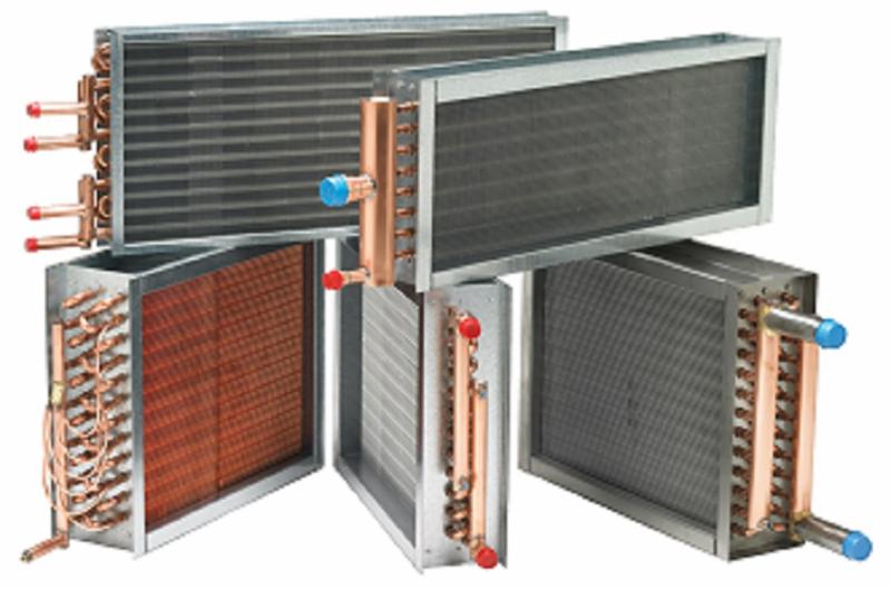
Typical booster coil design
Typically booster coils are a 1 or 2 row coil that achieves high performance by increasing water velocity obtained by the way they are circuited. Most ducts are sized for 800 to 1200 feet per minute (FPM) face velocity. This is about 9 – 13 miles per hour (MPH) and gives you an idea of the speed of air as it moves through the air duct.
Booster coils usually need to be sized between 500 to 750 FPM and require a “duct transition” in order to have the air slowed down to go through this larger face area coil. This is necessary to eliminate the risk of drastically increasing the working brake horsepower to produce the required volume of air.
Specific requirements needed to calculate a coil:
- The maximum height and length of the coil – This is needed to determine which way a coil that is above a ceiling or in-between joists can be expand to keep the air velocity at a reasonable speed.
- Required CFM volume of air
- Entering air temperature and either desired leaving air temperature or desired BTUH load required
- Entering water temperature and either desired leaving water temperature or desired GPM water volume – There’s a lot of difference between a coil selection at 180˚ F entering water and 140˚ F entering water temperature. There’s also a large difference when the leaving water is based on a 20 or 40 degree temperature difference (Example: 180˚ F in and 160˚ F out vs. 180˚ F in and 140˚ F out).
- Required maximum air resistance (inches of water)
- Required maximum water resistance (feet of water)
- Flange or slip and drive type mounting
- Coil construction – This will include fin thickness if you want to wash and clean coils and whether you want brazed copper sweat connections or threaded MPT connections.
Special booster coil situations
Occasionally a special situation may arise regarding a booster coil. Here are some typical situations you may encounter and how to alleviate problems.
- Low water flow – This can happen on many coils under 500 CFM, because the calculated water volume (GPM) is so low that the coil actually develops “laminar flow” – flow of water so low that it destroys heat transfer. This problem can reduce a coil capacity by 75 to 80 percent. Simply use a smaller diameter tube and the water velocity can usually be raised above 1 FPS.
- Air stratification – A coil’s efficiency is based on using the entire effective area of the coil, however unequal air flow can be created when entering air is too close to a fan or a bend in the ductwork. To reduce stratification a baffle or turning vanes may be required so the coil can receive air properly across the effective area.
- Lack of access – Dirty coils reduce heat transfer and increase resistance and operating expenses, yet many hot water coils are mounted in ducts so tightly that there is no access to the fins and tube surface. Simply provide access through a hand hole door to clean the coil at least every 4 to 5 years.
Contact Campbell-Sevey
Usually, a booster coil will not match up to the corresponding duct-work size. Air velocities through the duct-work are almost always higher than allowable coil face velocities, therefore transition needs to be done. Contact Campbell-Sevey if you have questions on how best to transition the duct-work to get to the coil.